Fusion 360 Electronics
The Future of Autodesk EAGLE
Autodesk blog: Our Path Forward with Fusion 360 Electronics [en] [jp]
- Effective June 7, 2026, Autodesk will no longer sell or support EAGLE. Moving forward, we will continue to invest our energy in Fusion 360 Electronics.
- EAGLE Free Subscribers: Fusion 360 for Personal Use is the suggested path forward. Fusion 360 for Personal Use is free and includes integrated CAD, CAM, and CAE functionality, up to two sheets per schematics, two Signal Layers, and a 80mm2 board area.
- Fusion 360 Subscribers: If you already use Fusion 360, the learning curve from Autodesk EAGLE to Fusion 360 Electronics will be minimal.
Fusion 360 Electronics Migration Guide for EAGLE Users
Autodesk EAGLE Announcement - Next steps and FAQ [en] [jp]
Ref. Autodesk Eagle
New Electronics Design
File -> New Electronics Design
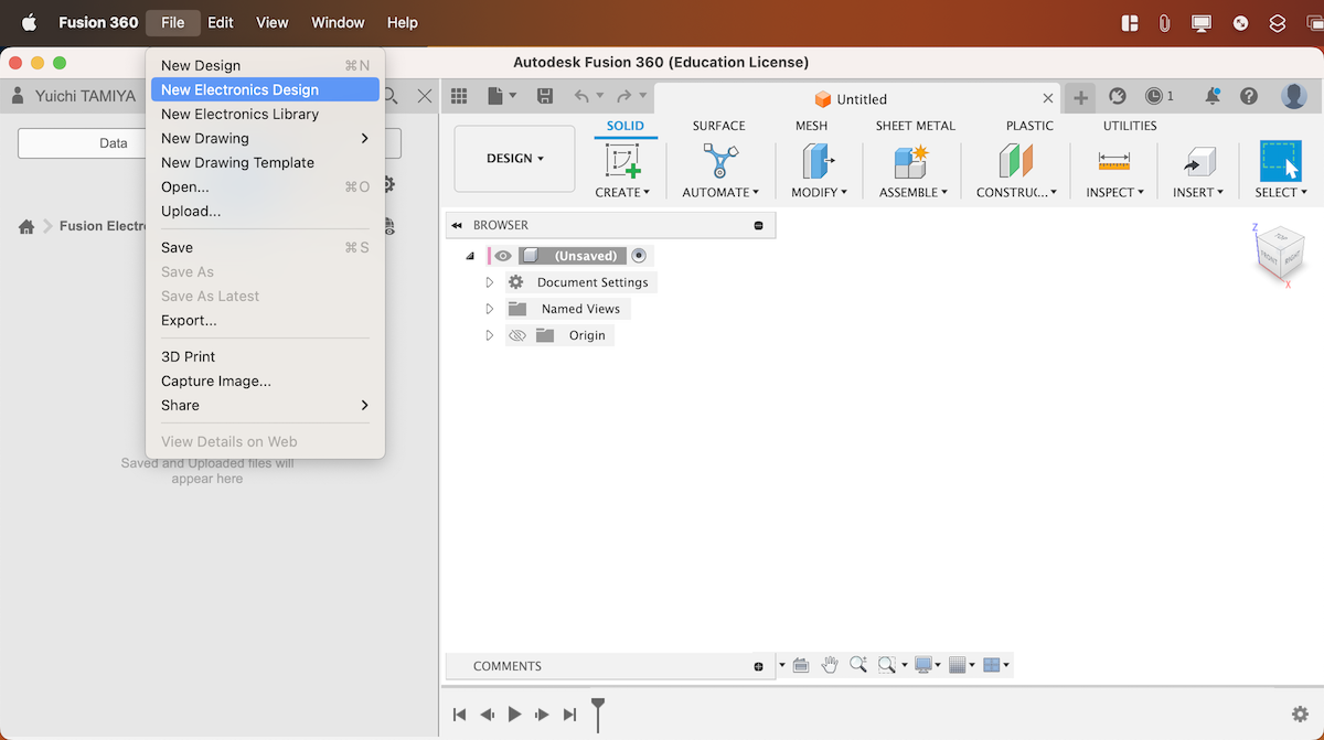
New Schematic
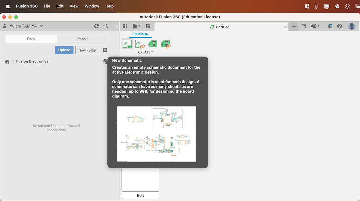
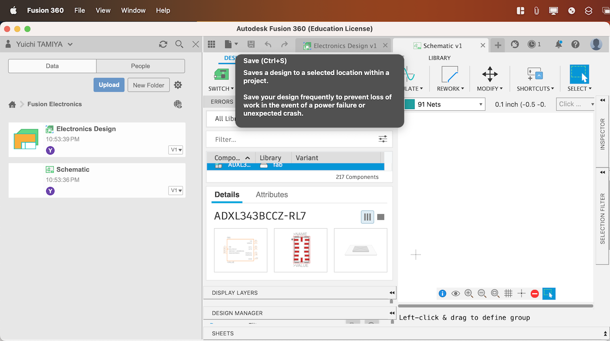
Save
Library
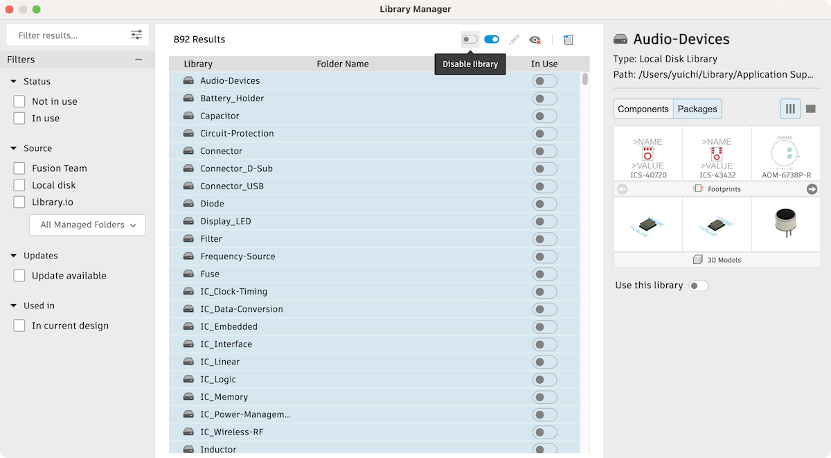
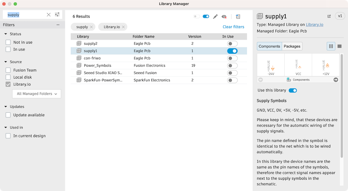
Open Library manager
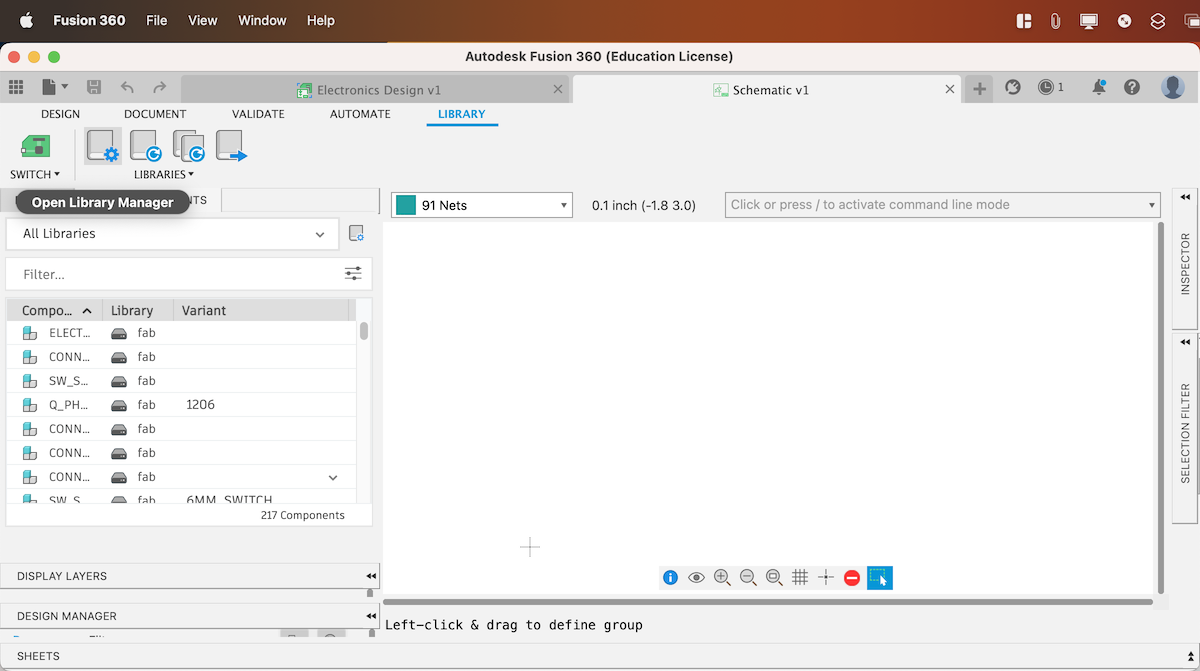
Select all -> Disable library
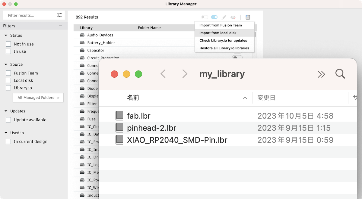
Download fab.lib and Import it from local disk
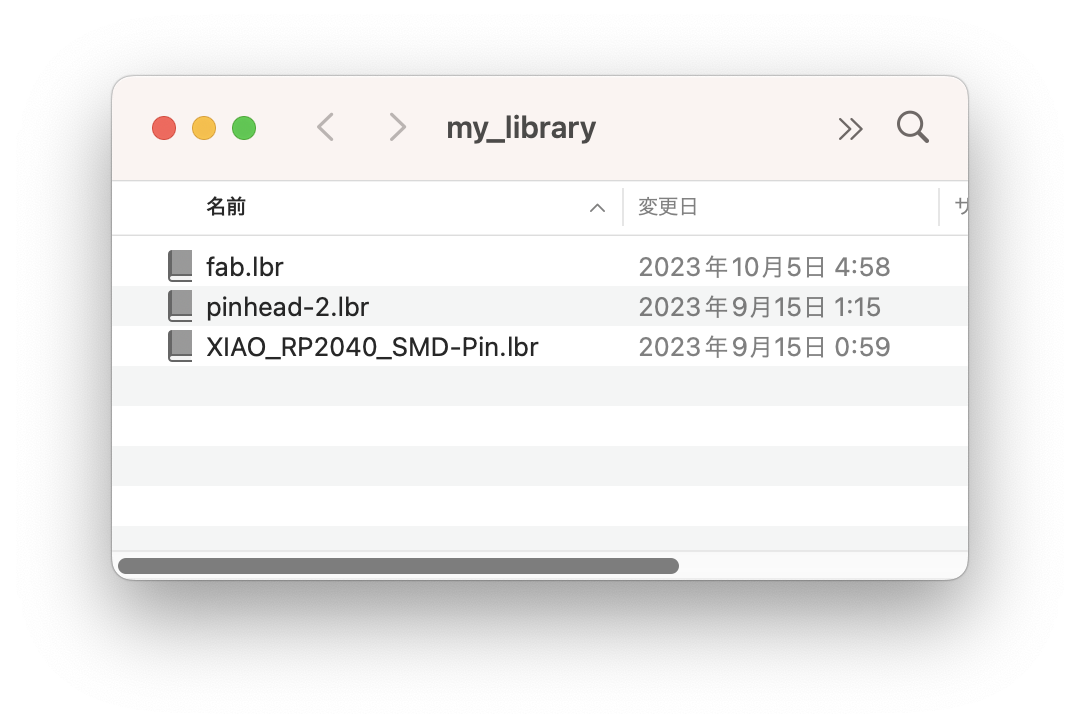
Note
For Better libraries management, create my_library folder and place all downloaded .lib file in it
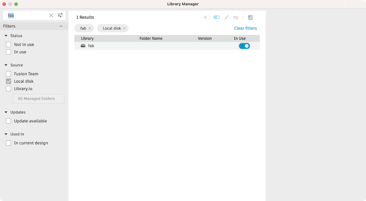
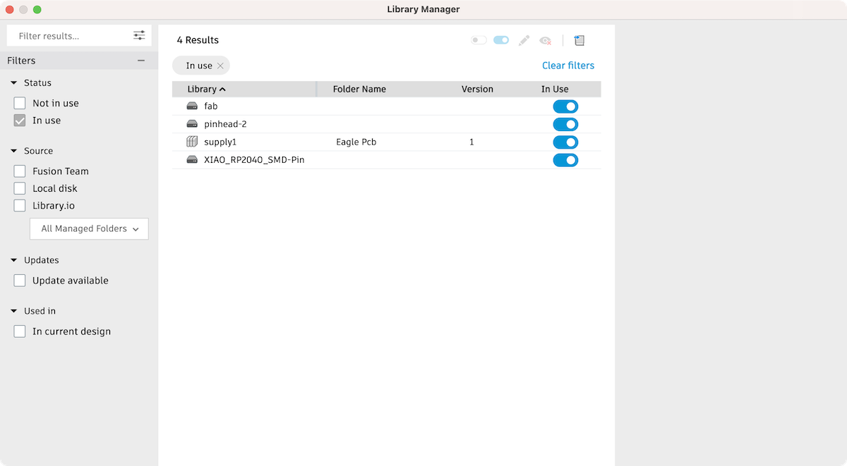
Search fab and set the status to In Use
Search supply1 and set the status to In Use
Download pinhead-2.lib, XIAO_RP2040_SMD-Pin and others, import them and set all to In use
Libraries
User Language Program (ULP)
Ref. FA2020
Drill Holes making
Command
SET FILL_LAYER 116 1;
run drill-aid 0
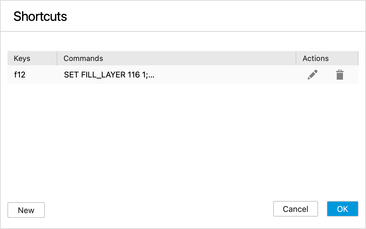
SET FILL_LAYER 116 1;run drill-aid 0 -> press F12 to assign the key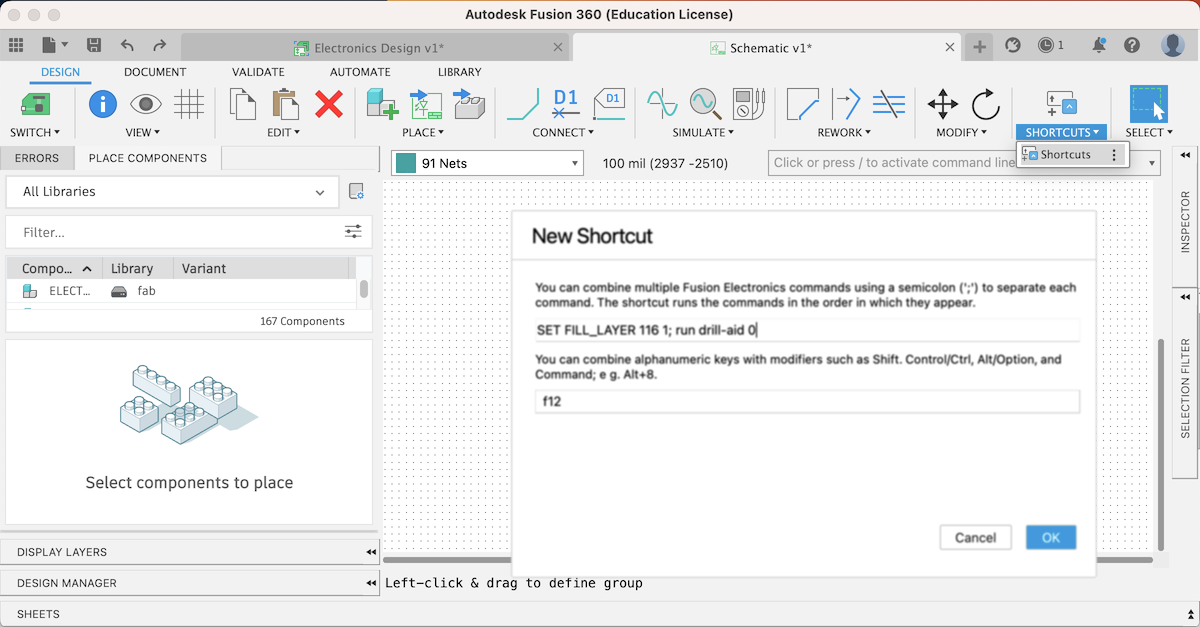
Schematic
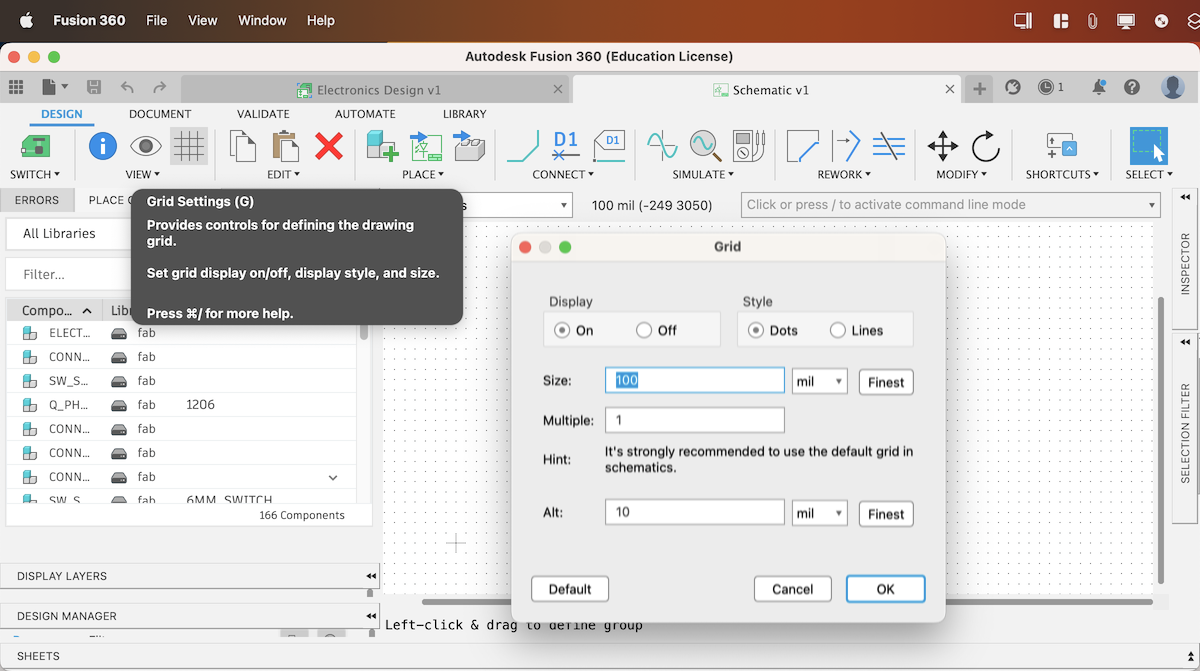
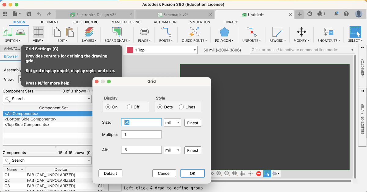
Grid
Set Grid On
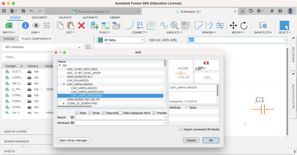
Add component from library
Press / to active command line mode and type add
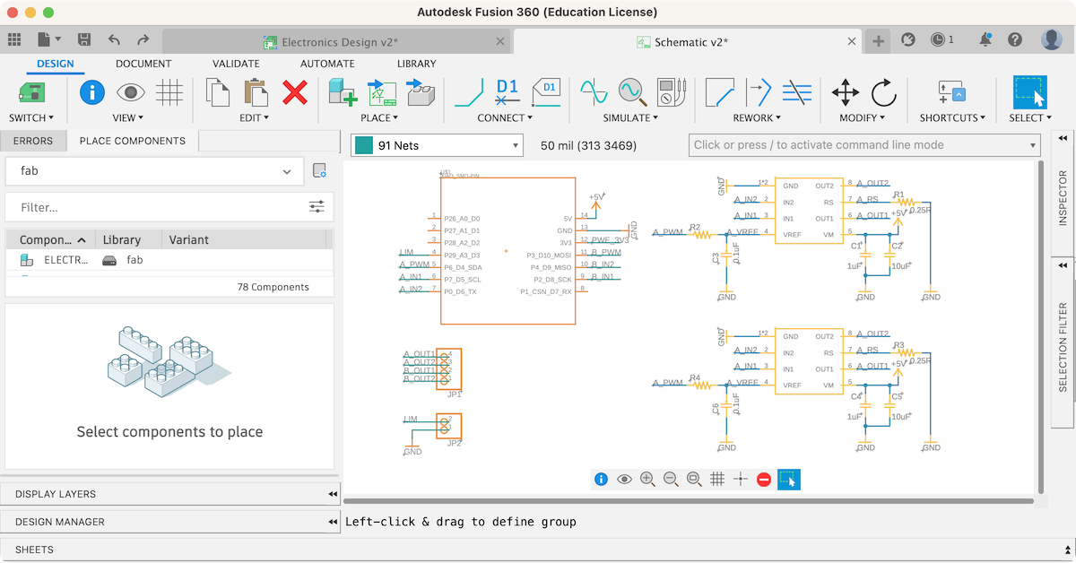
Xiao_RP2040_H-Bridge
Command
| Command | command line mode | Short cut key |
|---|---|---|
| Place component | / add |
a |
| Net | / net |
r |
| Name | / name |
n |
| Value | / value |
v |
| Move | / move |
m |
| Copy | / copy |
command/control + c |
| Delete | / delete |
command/control + c |
| Group copy | / copy -> Right click -> select Groupe Copy |
command/control + c -> command/control + v |
| Groupe move | / move -> Right click -> select Groupe Move |
Drag by mouse |
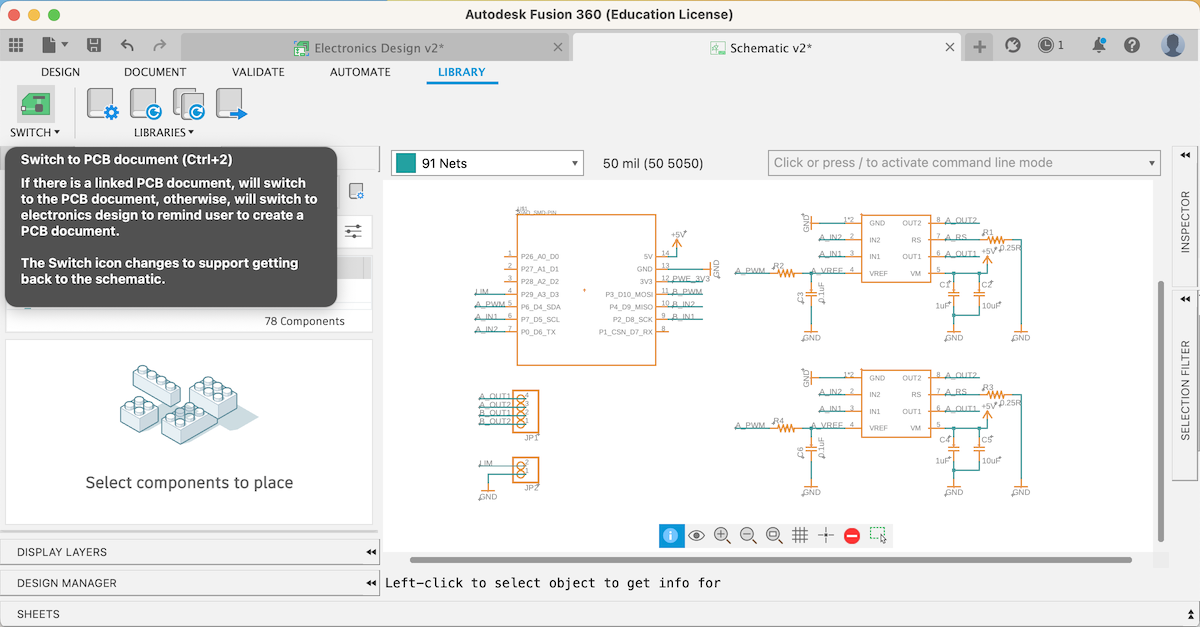
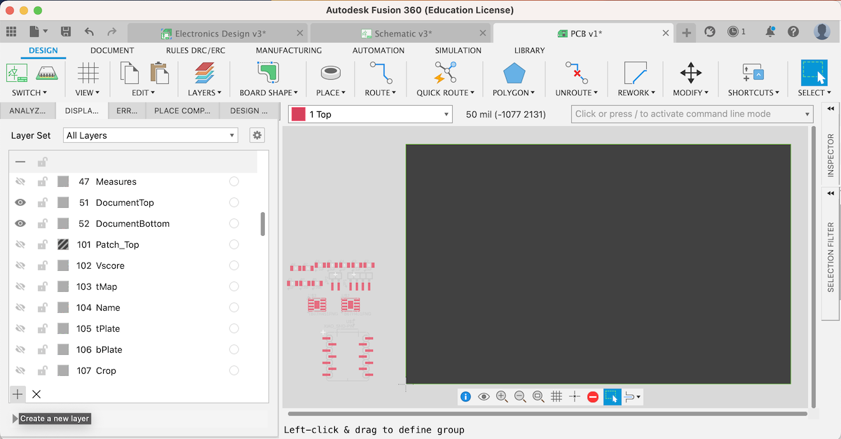
Switch to PCB Document
Grid
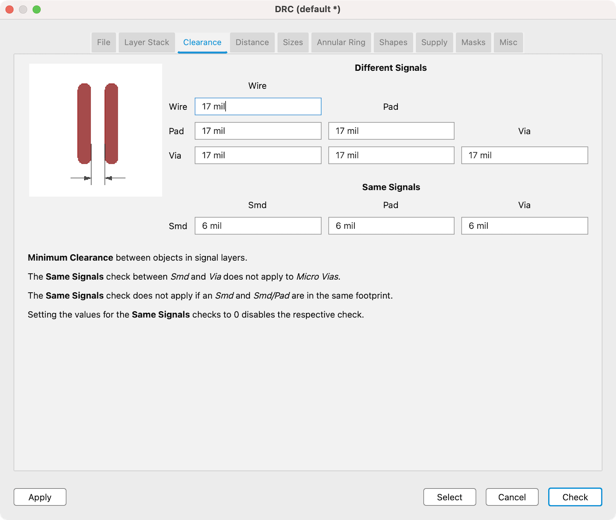
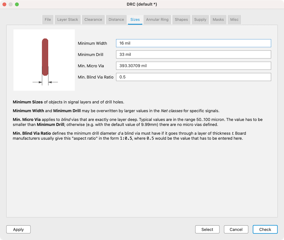
DRC
/ drc
Note
Endmill size
- Trace: 1/64”(16mil)= 0.39688 mm
- Outline and holes: 1/32” = 0.79375 mm
To create a tool path, the clearance must be greater than the end mill size. According to my test, to set the clearance to 1/17 mil (0.4318 mm) give a better result with the end mill size of 1/64”.
Outline for milling
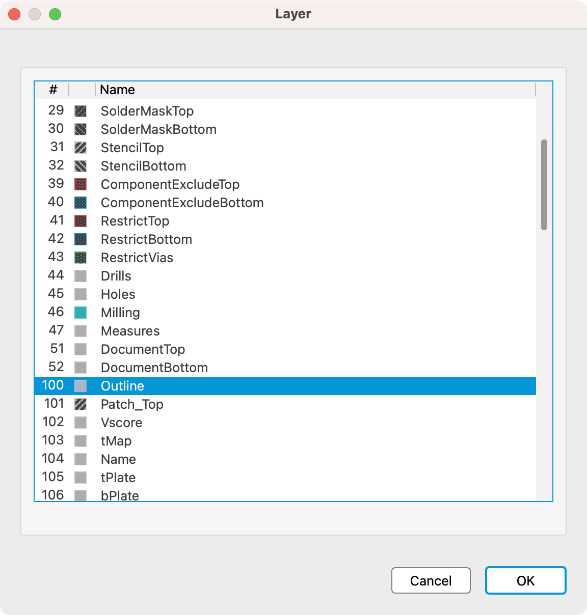
Create new layer and name outline
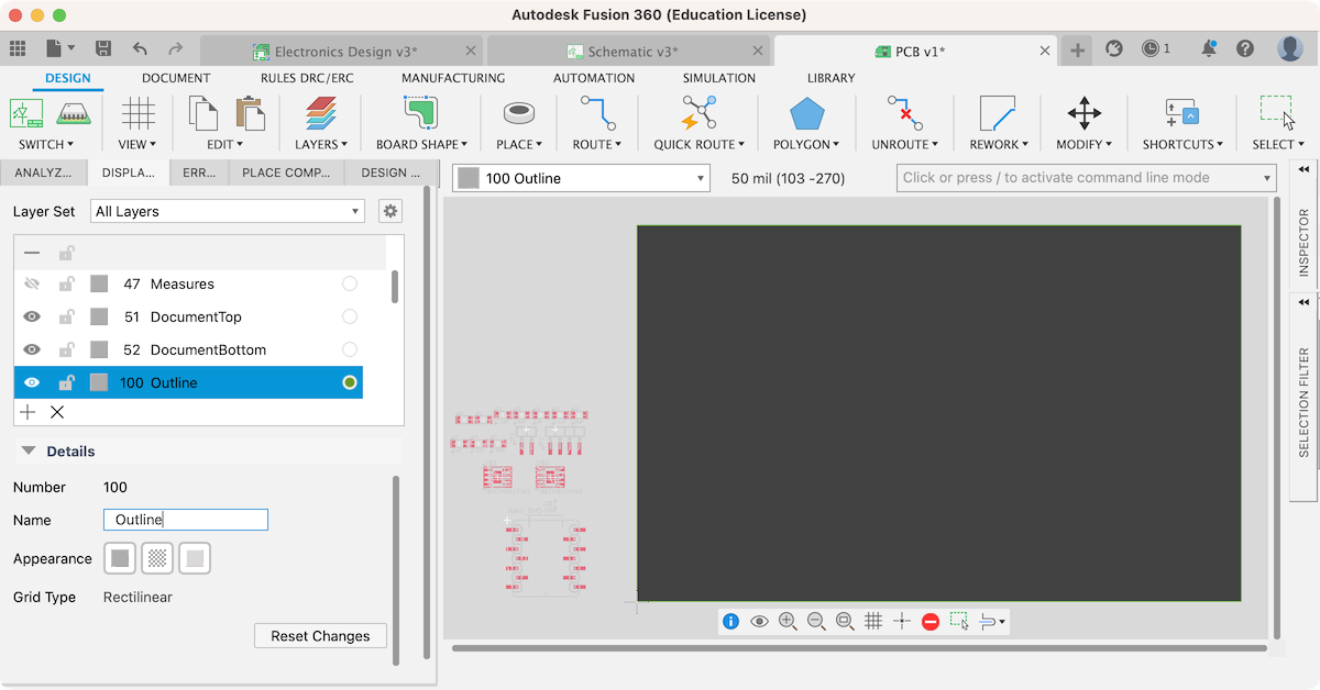
Select layer 100 and / and line command
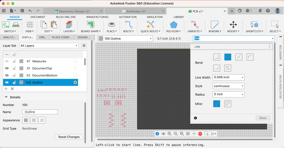
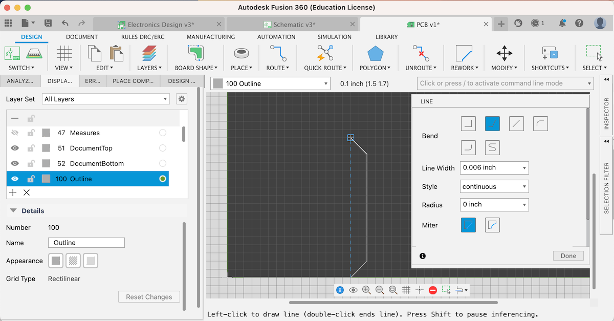
Draw closed shape by line
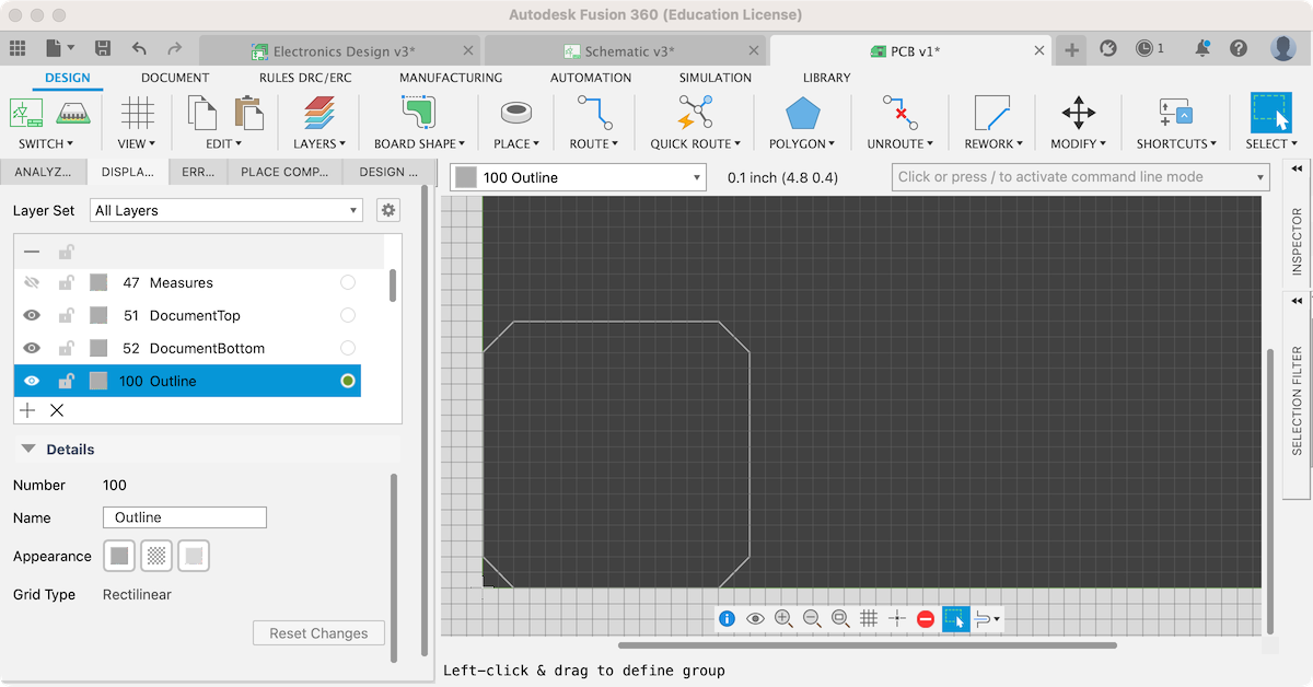
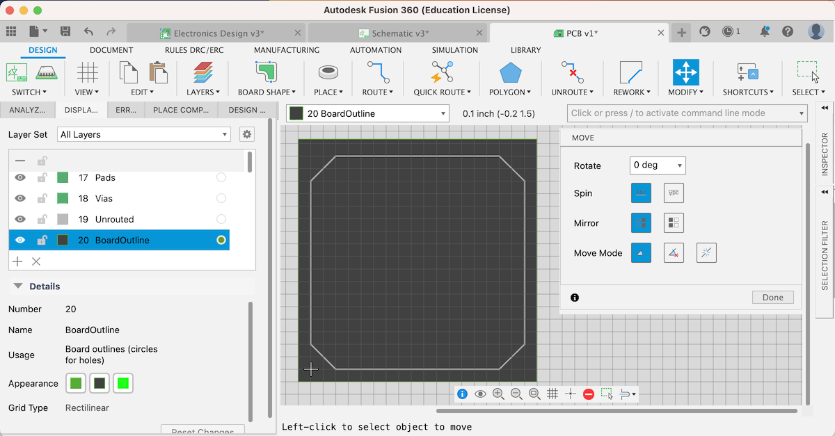
Select layer 20 BoardOutline and move green lines to show the entire outline shape
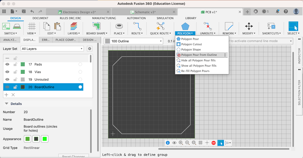
Use Polygon Pour from Outline and click outlines to be filled on Layer100
Select layer 100 Outline
/ and export in command line
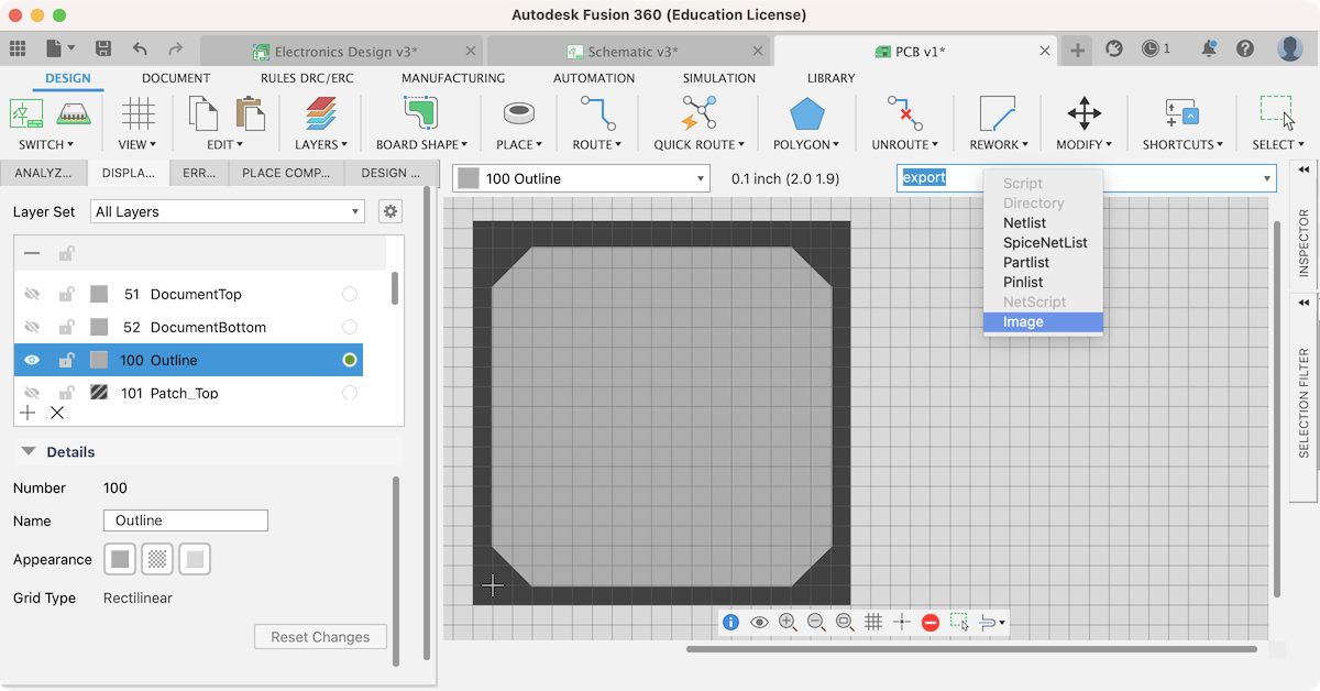
Export outline as Monochrome PNG
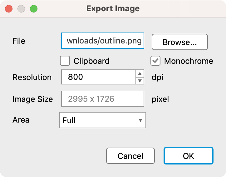
If all compornents are inside the outline shape, you will get this result

For milling
Undisplay signal names on pads and traces
/ and set
Select the tab Mi…(miscellaneous) and off Display singal names
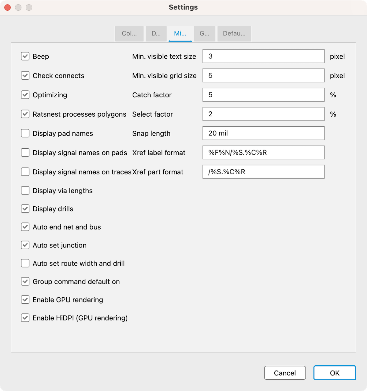
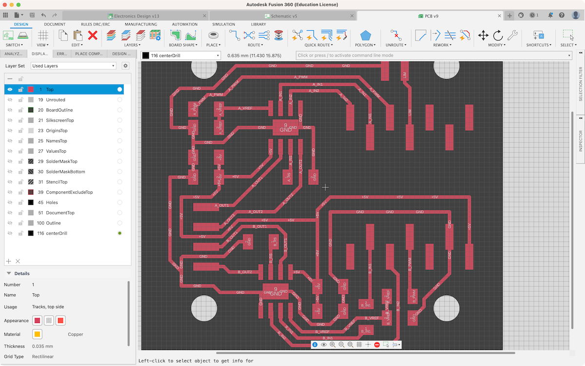
Undisplaied signal names. Ready to export Top PNG

Make drill holes
Set ULP -> see Drill Holes making
SET FILL_LAYER 116 1;
run drill-aid 0
Press F12key
Turn view on Layer 116 centerDrill