Program AVR 1-seriese from UPDI
file:///Users/yuichitamiya/Library/Arduino15/packages/megaTinyCore/hardware/megaavr/1.1.5/variants/ file:///Users/yuichitamiya/Library/Arduino15/packages/megaTinyCore/hardware/megaavr/1.1.5/variants/txy4/pins_arduino.h
static const uint8_t PIN_PA4=0;
static const uint8_t PIN_PA5=1;
static const uint8_t PIN_PA6=2;
static const uint8_t PIN_PA7=3;
static const uint8_t PIN_PB3=4;
static const uint8_t PIN_PB2=5;
static const uint8_t PIN_PB1=6;
static const uint8_t PIN_PB0=7;
static const uint8_t PIN_PA0=11;
static const uint8_t PIN_PA1=8;
static const uint8_t PIN_PA2=9;
static const uint8_t PIN_PA3=10;

#define PINS_COUNT      (12u)

#ifdef ARDUINO_MAIN

// On the Arduino board, digital pins are also used
// for the analog output (software PWM).  Analog input
// pins are a separate set.

// ATtiny1614 / ARDUINO
//                          _____
//                  VDD   1|*    |14  GND
// (nSS)  (AIN4) PA4  0~  2|     |13  10~ PA3 (AIN3)(SCK)(EXTCLK)
//        (AIN5) PA5  1~  3|     |12  9   PA2 (AIN2)(MISO)
// (DAC)  (AIN6) PA6  2   4|     |11  8   PA1 (AIN1)(MOSI)
//        (AIN7) PA7  3   5|     |10  11  PA0 (nRESET/UPDI)
// (RXD) (TOSC1) PB3  4   6|     |9   7~  PB0 (AIN11)(SCL)
// (TXD) (TOSC2) PB2  5~  7|_____|8   6~  PB1 (AIN10)(SDA)
//
//
Attiny412
ATtiny1614
ATtiny3216
ATtiny3217
Supported Clock Speeds
- 20MHz Internal (4.5v~5.5v - typical for 5v systems)
- 16MHz Internal (4.5v~5.5v - typical for 5v systems)
- 10MHz Internal (2.7v~5.5v - typical for 3.3v systems)
- 8MHz Internal (2.7v~5.5v - typical for 3.3v systems)
- 5MHz Internal (1.8v~5.5v)
- 4MHz Internal (1.8v~5.5v)
- 1MHz Internal (1.8v~5.5v)
NOTE
These parts do not support using an external crystal like the classic ATtiny parts
Arduino Sketch
Button
Arduino IDE > File > Example > 02.Digital > Button
// constants won't change. They're used here to set pin numbers:
const int buttonPin = 2;     // the number of the pushbutton pin
const int ledPin =  13;      // the number of the LED pin

// variables will change:
int buttonState = 0;         // variable for reading the pushbutton status

void setup() {
  // initialize the LED pin as an output:
  pinMode(ledPin, OUTPUT);
  // initialize the pushbutton pin as an input:
  pinMode(buttonPin, INPUT);
}

void loop() {
  // read the state of the pushbutton value:
  buttonState = digitalRead(buttonPin);

  // check if the pushbutton is pressed. If it is, the buttonState is HIGH:
  if (buttonState == HIGH) {
    // turn LED on:
    digitalWrite(ledPin, HIGH);
  } else {
    // turn LED off:
    digitalWrite(ledPin, LOW);
  }
}
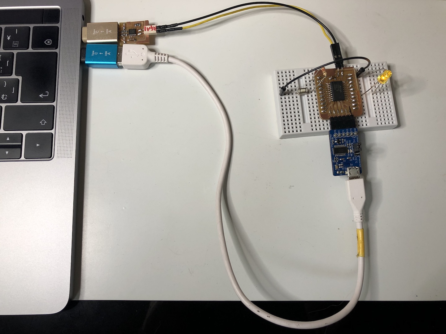
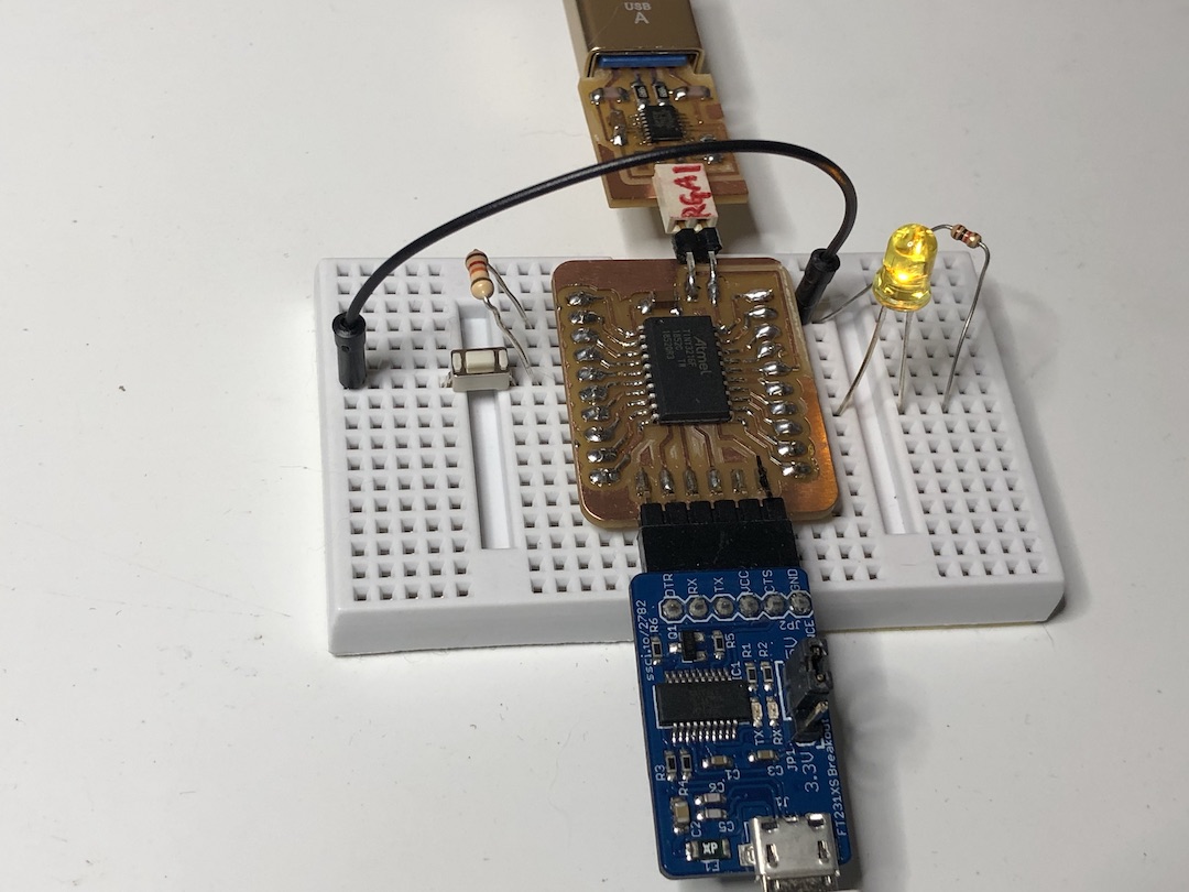
my ATtiny3216_breadboard
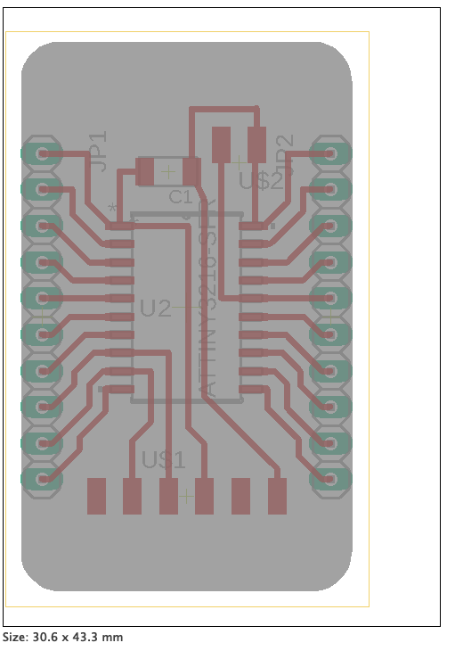
Connection
const int buttonPin = 2; // the number of the pushbutton pin
Connection
- Button to 2 (PA6) and GND
- Pull up Resister(10k) between 2 (PA6) and VCC
const int ledPin = 13; // the number of the LED pin
Connection
- LED(+) to 13 (PC3)
- LED(-) to Current limited Resister(1k)
- Current limited Resister to GND
Programme
on Arduino IDE
- open sample sketch Button
- Tool > select setting
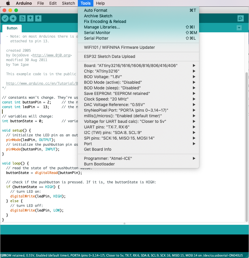
- Compile

$ cd Arduino/build/
$ ls
Button.ino.hex
updi programmer
- connect updi programmer
$ ls /dev | grep usb
cu.usbserial-D307RGA1
tty.usbserial-D307RGA1
-
connect FTDI for power supply
-
program
- ref.mypage
$ python3 pyupdi.py -d tiny3216 -c /dev/tty.usbserial-D307RGA1 -b 57600 -f Button.ino.hex -v

if error

$ which pyupdi.py
/Users/yuichitamiya/bin/pyupdi.py
$ python3 /Users/yuichitamiya/bin/pyupdi.py -d tiny3216 -c /dev/tty.usbserial-D307RGA1 -b 57600 -f Button.ino.hex -v